How to build a USB adapter for the G29 Shifter
Another day, another adapter

So you've upgraded from your trusty G29 to a fancy direct drive wheel and now you're stuck with a perfectly good shifter collecting dust? Same here! In this post, I'll show you how I hacked together a simple adapter using a Raspberry Pi Pico that lets you use that G29 shifter as a standalone USB device. This little weekend project saved me about $300 compared to buying a new shifter—and honestly, it was pretty fun to build.
I'm not going to pretend this is some groundbreaking innovation (others have done similar projects), but if you've got some basic soldering skills and can follow simple instructions, you can breathe new life into your old Logitech gear.
Background
Since my last project build log I fell deep into the sim racing rabbit hole. As I touch on in new years post, I had the chance to checkout my first direct-drive sim setup at the F1 Exhibition in Toronto. After experiencing that setup first-hand, I found it so tough to go back to my Logitech G29. So I sold my G29 wheel and pedals, but kept my shifter.
My first upgrade were my pedals. I purchased the SimJack Pros from AliExpress with hydralic dampeners. I only paid ~ CAD$ 300 and was night and day compared to the G29 pedals. After using them for a couple weeks I totally understood why people recommend updating pedals first out of all sim equipment. The extra travel in the brakes give you so much more control over your inputs
The only problem I had with these new pedals was that I had nowhere to mount them. I ended up building a wooden mount, but it was really unstable to use and it kept shifting under braking.
In November I took the plunge and ordered a Simagic Alpha + GT Neo bundle from SimRacingPros and an ASR-3 Gen2 from Advanced Sim Racing. With the chassis assembled and the wheel and pedals mounted, my sim racing experience has never felt more realistic. I feel so connected with my virutal car and the direct-drive allows me to catch slides never possible in the G29.
After getting that all setup I realized I had actually lost functionality compared to my G29 setup– I reverted back to a system without a dedicated shifter! While paddle shifters are great for F1 and GT racing, I still required an H-pattern shifter for city cars in Assetto Corsa Evo and BeamNG .
Build Log
Requirements
- G29 Shifter (duh)
- Raspberry Pi Pico
- Female DB9 port (or a male one with an adapter)
- Wires, I used a CAT6 cable
- Soldering Iron
Research
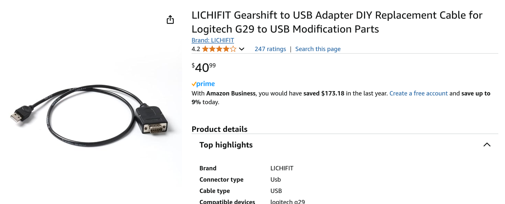
The first thing to do when building these bespoke adapters is to do a quick search to see if someone else has attempted a similar project. I took a look on Amazon and I found a simple looking adapter being sold, so I knew the project was viable.
The main thing I was interest in for my research was the pinout for the shifter, specifically what wire corresponds to what function. I knew from my experience building the pedal adapter the pinout should be relatively simple. With a quick search on GitHub, I found a comprehensive pinout, all thanks to Armando Iglesias for providing it!
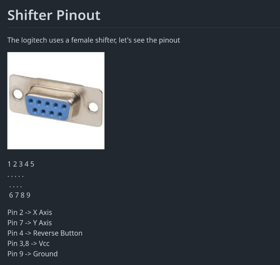
According to the pinout, the shifter operates on a fairly similar principle, to the pedals. It uses two potentiometers (X and Y axis) to determine the position of the stick and a button that acts when you push down for reverse.
Hardware Development
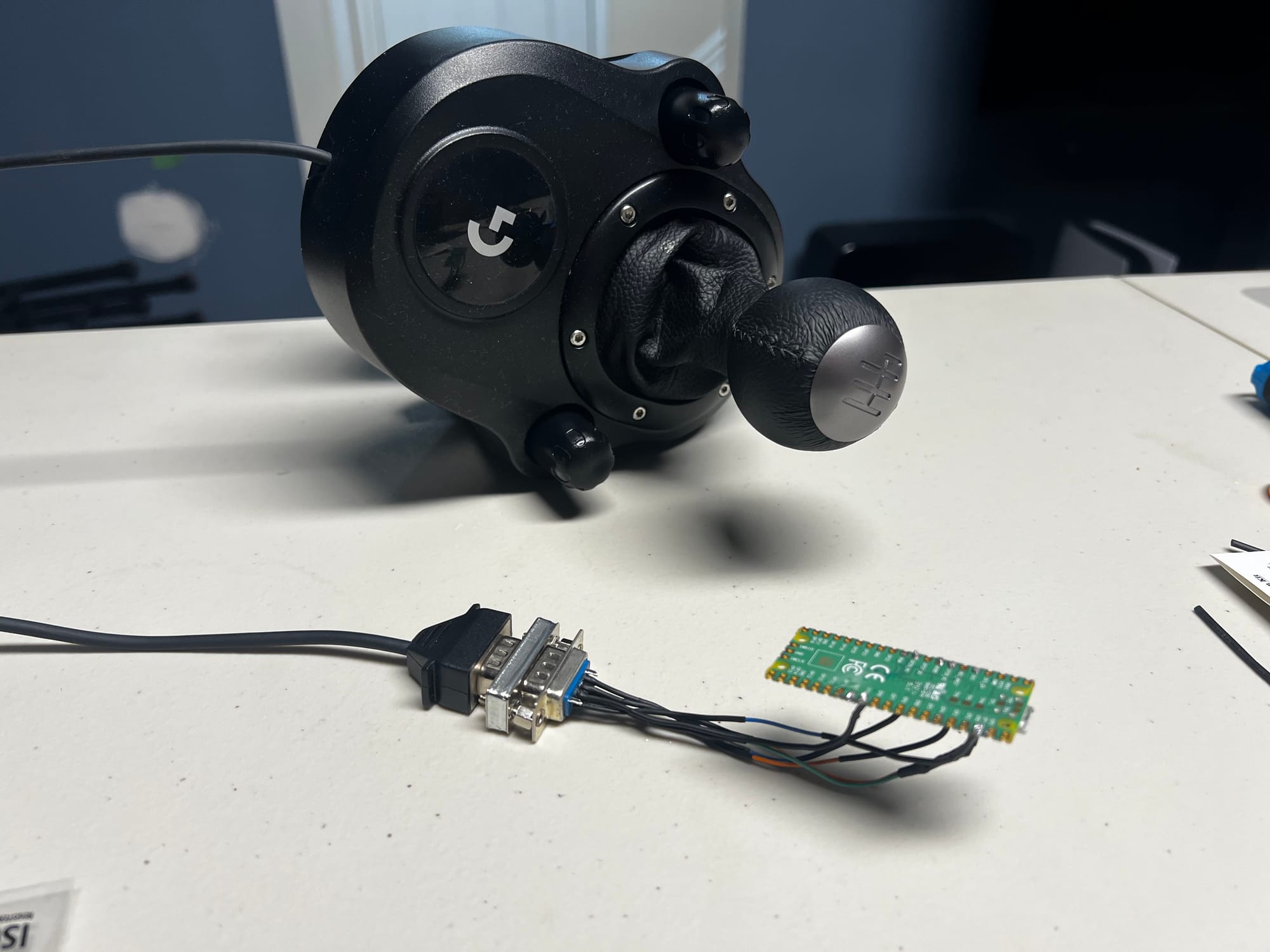
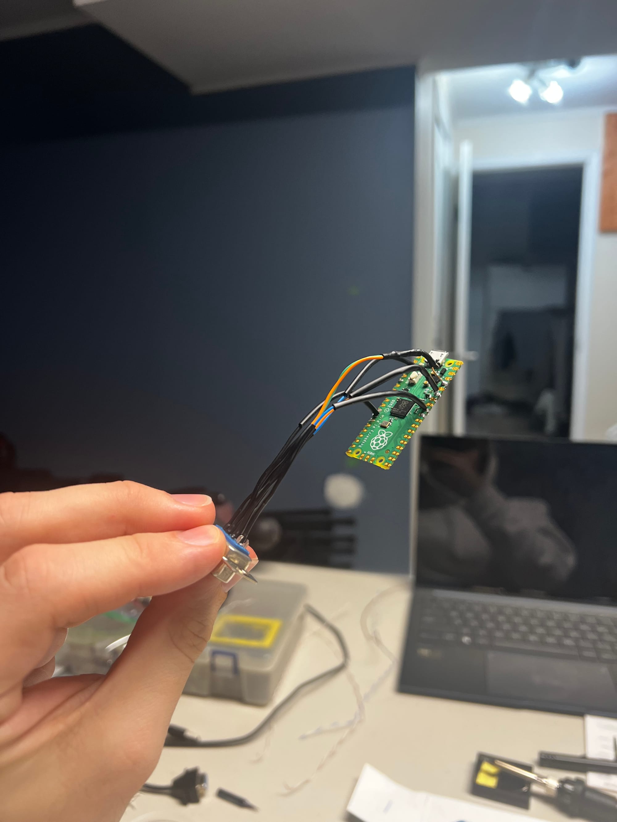
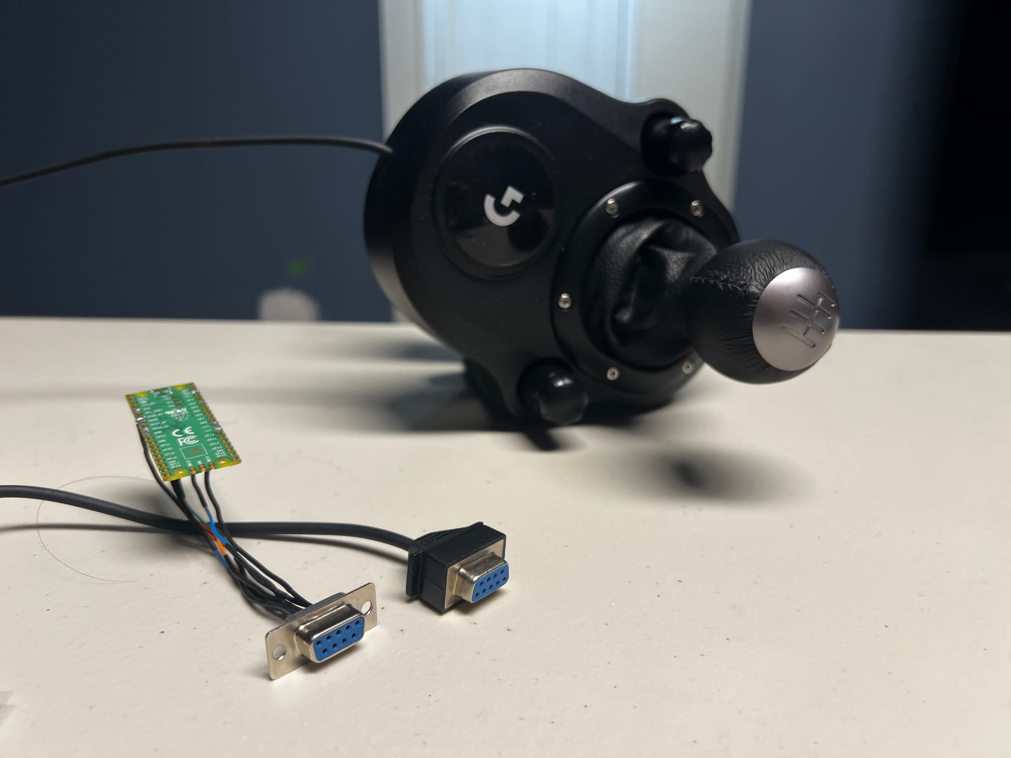
Using the above pinout for the shifter, it was a pretty easy job to solder everything up to the Pi Pico. The wiring was simpler than my pedal adapter project - I just needed to connect the X and Y axis wires to the ADC pins , push button to a GPIO pin, VCC to 3v3, and the ground.

I tried to always follow the "Measure Twice, Cut Once" mantra that I learned back in my high school wood shop class, meaning always double check your measurements (in this case, project design) before taking action. Well, I assumed the shifter would use the same connector type as the pedals and didn't really think about it until I went to test the adapter after soldering everything together.
And that's when I realized both plugs were female 🤦♂️
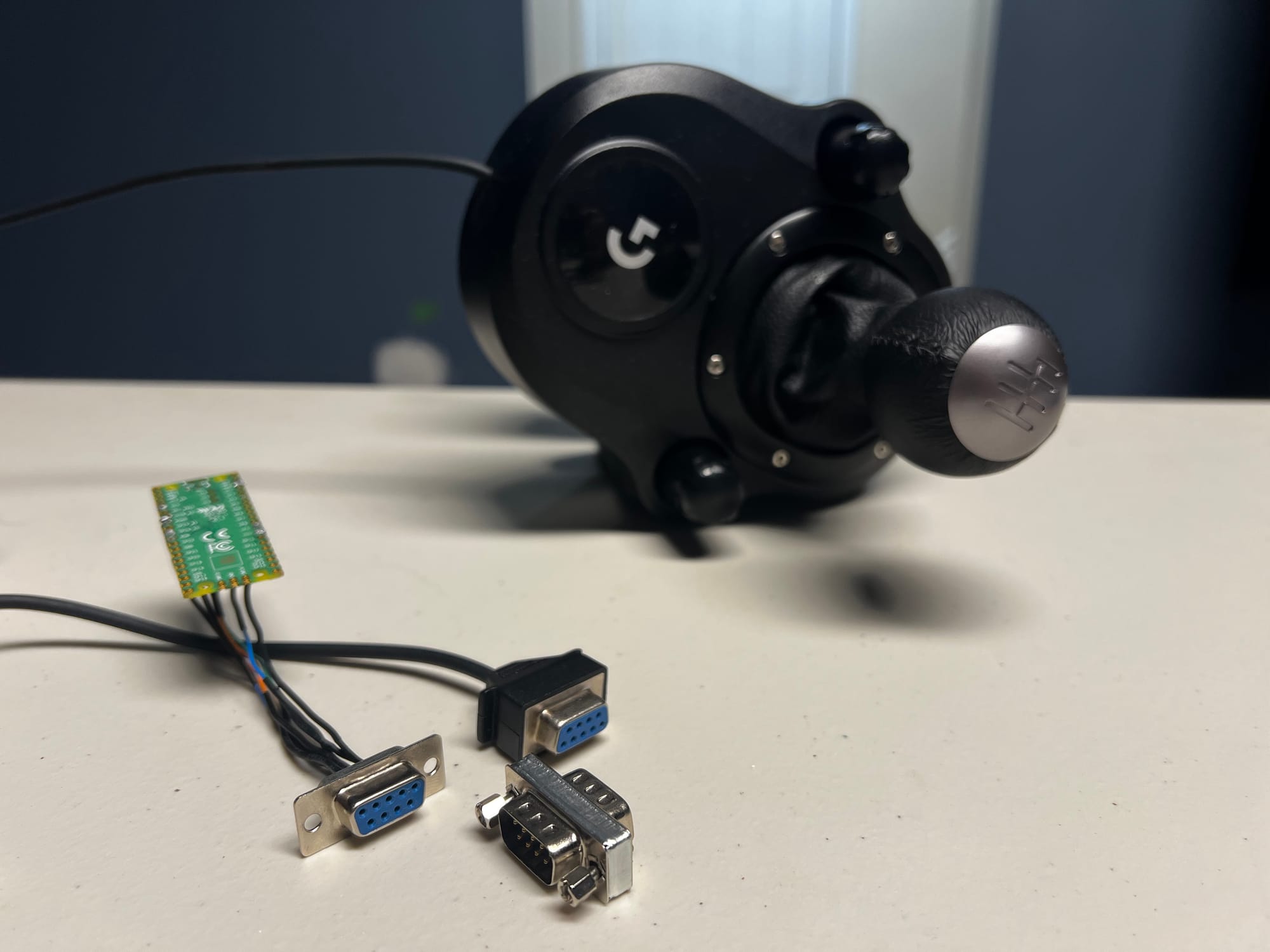
I could've purchased a new plug and re-soldered everything again, but I was feeling lazy and just wanted the adapter to work. Also shipping on the male plug was outrageous.
Instead I bought a DB9 male-to-male adapter to bridge the gap. It's definitely not the most elegant solution but I'm the only one using this adapter and it works for me!
Software Development
With all the hardware sorted, it was now time to write the code. The shifter outputs XY axis positions with a digital button signal. So the code simply had to map the XY position into gear 'slots' and to use the button as a modifier for the reverse gear.
Unlike my pedal adapter project, I used the Arduino Joystick library instead of the PicoGamepad library. The reason for this is due to a compiler error in the PicoGamepad library that wasn't allowing me to build my project using the new device target in the Arduino IDE.
The code is linked at the bottom of this blog post.
Testing
Testing was pretty straightforward! My first test was to output a log of all the inputs to the serial monitor to make sure all my solder connections were solid (and I didn't accidentally fry something).
After flashing the Pico with my shifter code, everything worked flawlessly! I booted up Imola on the new Assetto Corsa Evo early access version to test it out with an actual car.
Demo! I should've picked a car with 6 gears...
Future
This project is functional, but there's always room for improvement:
- Implement a sequential mode. I've been wanting to get into EA WRC and a sequential mode would be pretty easy to implement.
- Design and 3D print a case for the adapter
- Create a configuration app / script to adjust the shifter mode without the need for a hardware button.
- Implement the project using TinyGo. I've been learning Go at work and I think it would be a fun learning experience
Recap
Not only did this adapter save me $300 by allowing me to reuse a device I already own instead of buying a new standalone shifter, it also prevented a perfectly usable device from getting tossed away.
The project took me about 5 hours in total - most of which was fixing solder joints from my cheap $20 iron from Amazon.
One unexpected benefit is that my new shifter is actually more responsive than when it was connected through the G29 wheelbase!
Resources
Have you built any custom adapters? I'd love you hear about your projects in the comments!